Explore Products by Category
Featured Products
Countless Power Control Applications
Reliability, silent operation, and unparalleled life expectancy make HBControls’ solid-state power controllers an invaluable component in a wide range of industrial and commercial applications. These include medical ovens, incubators, sterilizers, professional cooking equipment, beverage systems, HVAC & refrigeration systems, electric motor control, underfloor heating, renewable energy solutions, tankless water heaters, plastics machines and dryers, lighting systems, and more.
Why Choose HBControls
“HBControls has been an exceptional supplier of my electrical switching requirements. I can depend on HBControls to furnish me with an engineered solution and/or product that will perform as needed for my power control application(s). Engineering expertise, on-time deliveries and dependable, consistent customer service makes HBControls a highly reliable Power Controller and solid state relay provider to CLEVELAND COMPONENTS!”
“For years I relied on HBControls to provide quality power controllers and solid state relays for commercial cooking equipment. Quality, delivery, technical support and customer service are paramount for keeping customers happy, and HBControls has a superb track record for each. HBControls is extremely knowledgeable, and very quick and easy to work with on both standard products and custom designs. I can’t say enough about how pleased I am in all aspects of the products and service that HBControls provides.”
-
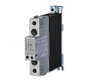
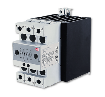
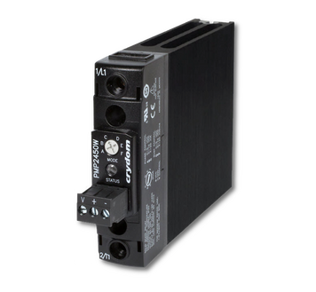
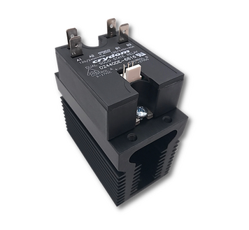
What is a solid state relay power controller?An HBControls Power Controller is a solid-state relay pre-assembled onto either a DIN or panel-mount heat sink. Each Power Controller is ready-to-use, eliminating the need for thermal calculations or heat sink selection. The maximum allowable load current for the assembled solid-state relay in a 40°C ambient temperature is provided in the datasheet for each controller. Solid-state relays are electronic relays that, unlike electromechanical relays and contactors, have no moving parts. As a result, their lifespan is significantly longer than comparable electromechanical relays. The typical MTBF (mean time between failures) for a solid-state relay is >7 million hours. Solid-state relays can also operate significantly faster, with on/off times measured in cycles rather than seconds. An instantaneous (also called a "random turn-on) solid-state relay can switch power to a load is less than 100µS. Solid state relay power controllers are similar to electromechanical relays and mercury contactors in terms of functionality. All of these devices switch power to or from an electrical load upon the application of an input or control signal. As previously mentioned, solid-state relays contain no moving parts, making them faster, quiet and highly reliable. Some of the benefits of using a solid-state relay power controller are: * Longer life expectancy and number of operations * Resistant to shock and vibration * Silent operation - no acoustical noise * Fast response time * No mechanical or moving parts
-
What is the difference between a Power Controller, electromechanical relay and a mercury contactor?"In terms of function, all three switching technologies are very similar to each other. That is, each switches power to/from an electrical load when voltage is applied to their input. However, electromechanical relays and mercury contactors utilize mechanical contacts to perform the switching function. HBC Power Controllers utilize solid state relays, which have no moving parts and perform the switching function exceptionally fast without any acoustical noise. The lack of moving parts also means that the life expectancy of a Power Controller is significantly longer than a comparable mechanical relay.
-
What is the difference between an AC output Power Controller and a DC output Power Controller? Can they be used interchangeably?The most common AC output Power Controllers utilize solid state relays with two back-to-back (inverse-parallel) SCRs in the output. These SCRs conduct load current when the AC sine wave is positive with respect to its anode. In other words, during a normal conduction cycle, one SCR will carry the full load current during ½ of the AC sine wave and the other will carry the load current once the polarity of the sine wave reverses. Most DC output Power Controllers utilize MOSFET solid state relays, which typically have a very low on-state impedance (Rds) and dissipate a minimal amount of power compared to AC output SSRs in applications below 100A of load current. Unlike AC output SSRs, DC controllers utilizing MOSFET SSRs can be wired in parallel to reduce power dissipation and effectively increase the maximum load-current rating. AC output controllers cannot be used to switch DC loads since the holding current of the SCRs will prevent them from turning off when the input signal is removed. The only exception is in applications where the load current is interrupted by other means. MOSFET controllers can be wired in inverse-series with the load to switch AC load current. This is an effective method for significantly reducing conducted emissions or minimizing power dissipation. However, since two relays are required the cost of doing so is often prohibitive. Consideration must also be given to the maximum off-state voltage rating of the controller, which can be damaged if exceeded by the peak AC voltage.
-
Why do solid state relays require heat sinks?AC output solid state relays are not perfect switches, having a forward voltage drop (Vf) of approximately 1Vrms when in the on state. Therefore, they dissipate power in the form of heat at a rate of about 1W per ampere of load current. An SSR switching 50 amps of load current will dissipate approximately 50W of power. For the sake of simplicity, if we assume that the thermal conductivity of air is 20°C/W, then the base plate of a solid state relay would reach roughly 1,000°C when carrying 50 amps while suspended in free-air. It would, of course, actually melt long before then, but the calculation makes the point. HBControls Power Controllers utilize highly efficient heat sinks to prevent the solid state relay from overheating during normal use. Datasheets for each controller provide maximum allowable current ratings in a given ambient temperature, eliminating the need for thermal calculations or heat sink selection.
-
Why does the load current rating of a solid state relay change when mounted to a heat sink?Because solid state relays dissipate heat in direct proportion to load current, and the fact that SSR life expectancy is dependent upon how well that heat is dissipated, the maximum allowable load current rating will almost always change whenever it is installed in an application. For example, a 90 amp solid state relay can carry 90 amps of load current only if it is mounted to a heat sink that can effectively dissipate 90W of power in the given ambient. If the heat sink is too small for 90W of dissipation, then the load current must be reduced to prevent the relay from overheating. Generally, it’s advised to keep the base plate temperature of an SSR below 80°C, although in many applications they can operate safely and reliably with a base plate temperature up to 100°C. If we wanted to switch 90 amps of load current in a 40°C ambient environment and keep the base plate temperature below 80°C, then we must prevent the base plate temperature from increasing by more than 40°C (80°C - 40°C ambient) while dissipating 90W of power. That means we would need at least a 0.44°C/W heat sink (+40°C allowable rise / 90W). If the same relay were mounted to a 2°C/W heat sink, for example, then the maximum allowable load current would be 20A (20A x 2°C/W = +40°C temperature rise). Without any type of external heat sink, most AC output solid state relays cannot carry more than 5 to 7 amps of load current in a 40°C ambient. The base plate of the relay helps dissipate some of the heat, but its thermal efficiency is limited by size. HBControls Power Controllers utilize highly efficient heat sinks to prevent the solid state relay from overheating during normal use. Datasheets for each controller provide maximum allowable current ratings in a given ambient temperature, eliminating the need for thermal calculations or heat sink selection.
-
What is thermal impedance and how does it apply to Power Controllers?Thermal impedance, or thermal resistance, is the measure of how resistant an object is to heat flow. The lower the impedance, the more efficiently the object will transfer heat. Thermal impedance is a critical aspect of Power Controllers as it determines how much power it can dissipate within a specified ambient temperature, which in turn determines how much load current it can effectively switch in an application. In most cases, the thermal impedance of a Power Controller is an irrelevant specification as full load-current ratings at different ambient temperatures are provided in the controller’s datasheet. However, understanding the importance of thermal impedance does help in understanding why heat sinks are required and vary in size for different ratings at different ambient temperatures.
-
What switching technology do Power Controllers utilize?HBControls Power Controllers utilize semiconductor-based relays to switch power to and from AC or DC loads. These relays typically utilize SCRs or MOSFETs for AC or DC loads, respectively. However, in some cases, diode or IGBT modules may be utilized when required within the application.
-
Why is the life expectancy for Power Controllers so much higher than the life expectancy of electromechanical relays and contactors?Electromechanical relays and contactors utilize mechanical contacts that are subjected to arcing every time they make (when closing) or break (when opening) power to / from the load. Over time, the arcing that occurs with each operation damages the contacts and eventually results in relay failure. The ‘heavier’ the load, the more significant the arc and the lower the life expectancy of the relay. Therefore, the life expectancy of an EMR typically ranges from 100,000 to 500,000 operations, which can be exceeded in just a few months in many industrial applications. Power Controllers utilizing solid state relays are not subjected to the same phenomena since they contain no moving parts. Power Controller life expectancy is usually given in hours and specified as mean-time-before-failure (MTBF) rather than operations. The typical MTBF of a Power Controller can vary between one million and ten million hours, or approximately 100 – 1,000 years.
-
What are the primary advantages and disadvantages of Power Controllers over electromechanical and mercury relays?Advantages; Life expectancy – Power Controllers can operate reliably for decades in most applications. Theoretically they can operate reliably for centuries but, since the first SSR was invented in 1972, that theory has yet to be proven. However, there are SSRs that have been in the field since the 70’s that are still operating normally and reliably. Silent operation – Power Controllers do not generate acoustical noise when switching power to/from the load since they contain no moving parts. Therefore, they are the preferred solution in many commercial or residential applications where acoustical noise can quickly become an annoyance. Shock & vibration resistance – Since Power Controllers have no moving parts they are not prone to false triggering under load in harsh environments subject to shock & vibration. Fast operation – Instantaneous turn-on Power Controllers can switch power to a load in less than 100 microseconds of receiving an input signal. This makes them ideal for phase-angle control applications where tight control over power to the load is required. PLC compatibility – As opposed to large contactors or other mechanical relays, Power Controllers can switch heavy loads with only a few milliamps of input current. Environmentally friendly – Power Controllers contain no mercury. Also, the abbreviated life expectancy of electromechanical relays means that hundred, if not thousands of EMRs will fail and have to be disposed before a single end-of-life Power Controller failure. Disadvantages; Cost – The initial purchase price of a Power Controller may be seen as prohibitive in some applications. However, due to the limited life of EMRs, the total cost of ownership of a Power Controller (the impact on cost over the life of the product in which it is used) is often significantly less than an equivalent rated EMR. Size – Power Controllers dissipate power in the form of heat during normal operation and therefore require an external heat sink in order to operate reliably. Galvanic isolation – Some applications require the load to be physically disconnected from the AC mains when in the off state. In these cases, the addition of a series electromechanical relay to provide off-state galvanic isolation might be the only viable solution. Energizing the EMR first in the sequence places the burden of switching full-load current on the SSR and significantly reduces or eliminates altogether the arcing of the EMR contacts, as does removing the input to the SSR just prior to de-energizing the EMR when switching to the off state.
-
What are zero-crossing and instantaneous (random or asynchronous) turn-on Power Controllers?Zero-crossing Power Controllers are the most common in the market. As the name implies, these controllers switch from a non-conducting to a conducting state shortly after the AC mains passes through the zero-crossing point of the sine-wave. Instantaneous turn-on Power Controllers will switch from a non-conducting to a conducting state within 100 microseconds of receiving an input signal. Both zero-crossing and instantaneous Power Controllers will continue to conduct load current after the input signal is removed until the AC sine-wave reaches the zero-crossing point. Therefore, the turn-off time is dependent upon exactly when the input signal is removed but will rarely be longer than 8.33 milliseconds on a 60Hz mains, or 10 milliseconds on a 50Hz mains.
-
When is it best to use a zero-crossing or instantaneous turn-on Power Controller?Zero-crossing Power Controllers are the most common in the market and will only turn on shortly after the AC mains passes the zero-crossing point of the AC sine wave. Therefore, there is only a minimal amount of voltage across the load when load current begins to flow, which means that there will also be a minimal amount of inrush current. Turning on close to the zero-crossing point of the sine wave also reduces the conducted emissions of the Power Controller and makes them more compatible with applications requiring some level of compliance with EMC standards. The general rule-of-thumb for zero-crossing SSRs is that they are suitable for use with loads having a power factor between 0.7 and 1.0, although some will function normally switching loads with power factors down to 0.5. Typical loads for zero-crossing SSRs include heating elements, some lighting systems and light inductive loads. They are not suitable for use in phase-angle control applications since they won’t turn on after the sine wave has passed their zero-crossing window, which is normally less than 30Vpk. Instantaneous (or “random”) Power Controllers will turn on within 100 microseconds of the input signal being applied. They are commonly used for heavier inductive loads, such as larger motors, transformers and low power-factor solenoid or contactor coils. They are easily phase-angle controlled and can therefore be used in lighting dimming systems or with heating elements in applications where tight control over power to the load is required.
-
What are phase-angle and burst-fire Power Controllers? Why would one technology be chosen over the other?Phase-angle controllers apply a portion of the AC power to the load by turning on at various point of each sine wave. The amount of power applied is dependent upon the input signal applied. For example, applying 5V to a 0-10V input controller would result in 50% power to the load. They are ideal for dimming applications or in heating systems where tight temperature control is required. They can also generate a significant amount of conducted emissions since they often turn on closer to the peak of the AC sine wave. Therefore, additional filtering is required when installed in applications requiring some level of compliance with EMC standards. Burst-fire controllers also apply proportional power but do so by providing a series of full AC cycles to the load. The number of full cycles applied is dependent upon the percentage required, which is determined by the control signal and the time-base period of the Power Controller itself. If the controller has a time-base period of 10 AC cycles and the control signal is set to 50%, then the Power Controller will turn on for 5 AC cycles and then off for the next 5 AC cycles. Burst-fire controllers are typically used in heating applications where tight control over temperature is required. They are also used in applications where proportional control is necessary, but there is a concern over the amount of conducted emissions placed on the AC mains. They are not commonly used for lighting applications since the on/off period can create a significant amount of flicker. Typical control options for both phase-angle and burst-fire controllers include 0-10V, 0-5V, 4-20mA and potentiometer input.
-
How quickly can a Power Controller switch power to / from a load?Instantaneous, or “random” turn-on Power Controllers can switch power to a load in less than 100 microseconds of the control signal being applied. Zero-crossing Power Controllers will not turn on until shortly after the AC cycle passes through the zero-crossing point of the sine wave. Therefore, they will begin to conduct load current within 8.33ms on a 60Hz line, or 10ms on a 50Hz line.
-
What type of isolation does a Power Controller provide between the control system and the load circuit?Power Controllers utilize optocouplers (also called optical isolators or photocouplers) to provide electrical isolation between the input circuit and the output power circuit that’s connected to the AC mains. There are several different types of optocouplers but the most common used in Power Controllers are triac drivers, or photo triacs. In addition to providing input-to-output isolation, the type of triac driver used in the circuit also determines whether the Power Controller is instantaneous or zero-crossing. DC Power Controllers typically use photovoltaic couplers. These devices generate enough voltage to quickly drive the output MOSFETs into full saturation, preventing linear operation of the MOSFETs to reduce power dissipation. Typical Power Controller optocouplers provide 4kVpk isolation between the input and output circuit, with 12mm creepage (along the surface of the PCB) and 6.4mm clearance (spacing directly between the pins).
-
What is off-state leakage current?When connected to the AC mains, a small amount of current will flow through semiconductor power circuits, even without the presence of an input signal. The amount of leakage current is typically very low - normally less than 1mA for AC output Power Controllers and only a few hundred microamps for DC output controllers – and not hazardous to personnel. However, even a small amount of leakage current can generate voltage across the load when the controller is in the off state. The amount of voltage is dependent upon the impedance of the load and often negligible but may become an issue in applications where compliance standards require that the load be physically disconnected from the AC mains in the off state. Leakage current can increase by a factor of 15 in Power Controllers with RC snubber networks (series resistor and capacitor) in the output circuit. This is because RC networks are configured in parallel with the output semiconductors and the impedance of a capacitor is inversely proportional to the frequency of the AC mains. The higher the frequency – 60Hz in North America – the lower the impedance of the capacitor in the snubber network.
-
What is dv/dt and how does it impact the performance of a Power Controller?Static dv/dt refers to the rate of voltage rise across the output of a Power Controller while it’s in the off state. Static dv/dt is also referred to as turn-on dv/dt because a static dv/dt failure is one where the Power Controller goes into conduction without the presence of an input signal. Commutating dv/dt, also referred to as turn-off dv/dt, is similar to static dv/dt but occurs when the Power Controller is conducting load current and attempting to turn off when the input signal is removed. Commutating dv/dt failures are normally associated with inductive loads, where the phase shift between voltage and current results in a high rate of voltage rise across the output when the semiconductors attempt to turn off as the load current nears zero. Neither type of dv/dt failure will damage the Power Controller. In the case of a static dv/dt failure the controller will simply carry load current for the remainder of the AC half-cycle and then turn off (<8.33ms on a 60Hz AC mains). Since only a small amount of power is passed to the load the result of such a failure is usually inconsequential. Commutating dv/dt failures can be more troublesome since the controller may conduct full-load current indefinitely when it’s expected to be in the off state. The typical maximum dv/dt specification for Power Controllers is 500v/µs but can be increased by the addition of an RC snubber network – either as and integral part of the controller design or wired externally across the output terminals. The addition of a snubber network will increase off-state leakage current but may be required in sensitive applications. These might include motors controlling equipment around personnel or motor-reversing applications, where the only separation of different phases of a three-phase voltage network is provided by an off-state semiconductor.
-
What is di/dt?di/dt refers to the rate of change in current through the output of the Power Controller with respect to time. Unlike dv/dt failures, If the maximum di/dt rating of the controller is exceeded, then the output circuit will be permanently damaged. The most common mode-of-failure is a shorted power circuit, typically in only one of the two output SCRs since only one SCR is conducting load current at any given time. This results in the half-waving of the load when the Power Controller should be fully in the off state. These types of failures most often occur in short-circuit load conditions. They can also occur because of a dv/dt failure with loads having high inrush-current characteristics, such as certain types of lamps or loads with a lot of capacitance. The maximum di/dt specification of most Power Controllers is 10A/µs. Unlike dv/dt prevention, RC snubber networks do not increase the maximum di/dt rating of a Power Controller. They can, however, minimize the likelihood of a dv/dt failure occurring that could potentially result in a di/dt failure. The most common form of di/dt protection is the addition of an air-core choke in series with the load since the reactance of an inductor increases as the rate of current change increases.
-
What is an RC snubber network and when should one be used?An RC snubber network is a series resistor and capacitor placed in parallel with the output of a Power Controller. They can be either be an integral part of the controller or connected externally to the output terminals. The primary function of the RC snubber is to attenuate the rate of voltage rise across the output terminals, which can result in a dv/dt failure of the Power Controller if their maximum rating is exceeded, which is typically 500v/µs
-
What is I2T?I2T is the fusing current for the output semiconductor of a Power Controller. It is a calculated value based upon the manufacturer’s published maximum single-cycle surge current rating for the device. It is intended to represent the amount of energy that the device can withstand before the silicon melts and fuses open. I2T is calculated by determining the peak single-cycle surge current rating (typically 10x the continuous forward-current rating of the controller), dividing it by the square root of 2 to get an rms value, squaring that number and then multiplying it by the AC half-cycle period (8.33ms for 60Hz or 10ms for 50Hz). The difference between di/dt and I2T is that di/dt is a rate of change of current and not necessarily associated with excessive amounts of current. While a di/dt failure normally results in a shorted die, I2T failures often destroy the output semiconductor and result in an open device.
-
What is the maximum allowable operating temperature for a Power Controller?Most HBControls Power Controllers are rated for their maximum load current in a 40°C (104°F) ambient environment with a 100% duty-cycle (on continuously). The amount of load current they can safely carry derates almost linearly to 0 amps at 80°C. However, these ratings include some amount of head-room to ensure that they operate safely and reliably in a variety of applications. Please contact us directly if you would like to discuss Power Controller performance in your specific application.
-
What is thermal fatigue and how does it impact the life expectancy of a Power Controller?A common misconception is that a high operating temperature can significantly degrade the life expectancy of a Power Controller. This is somewhat true, but it’s not the temperature itself that degrades controller life. Instead, it’s the amount of significant thermal excursions that the relay undergoes during it’s operating life that impacts overall reliability and life expectancy. Thermal excursions refer to how quickly the temperature of the components within the solid state relay of the controller fluctuates over time. A solid state relay dissipates power proportional to the amount of load current it’s conducting. The internal temperature of the SSR can rapidly increase, regardless of the amount of load current, if the heat sink is not adequate for the application. The rate in which the temperature fluctuates can stress internal components because the copper used to carry load current expands and contracts at a different rate than the solder used in the system. These excursions can “fatigue” the components over time, which may result in the premature failure of the SSR used on the Power Controller. HBControls Power Controllers utilize a range of efficient heat sinks to prevent excess heating and thermal fatigue. Active cooling solutions (cooling via forced-air flow) are also available for high-current applications or for applications where the controller is operated in high ambient temperatures.
-
What types of overvoltage protection are available for Power Controllers, and what are the differences?"Two options are available for protecting HBC Power Controllers from transient voltage spikes. The first is with a metal-oxide varistor (MOV), which is connected externally across the output terminals in parallel with the power semiconductors. The second is with a transzorb (transient-voltage-suppression diode, or TVS), which is internal to the SSR portion of the Power Controller and in parallel with the output section of the optical-isolator(s). Both devices are designed to suppress voltage spikes that exceed their specified rating, but the manner in which they do so differs. MOVs are similar to back-to-back diodes and will “avalanche” into conduction when the specified threshold of the device is exceeded. Since the MOV is in parallel with the output of the Power Controller, most of the energy from the transient will be passed through the MOV and into the load. The remaining energy is absorbed by the MOV itself and dissipated in the form of heat. These devices can quickly suppress transients, but the heat absorbed by the MOV will degrade its ability over time. The life of an MOV is ultimately determined by the number of transients it’s subjected to and the energy of those transients. TVS diodes are in parallel with the optocoupler circuit, which is in series with the gates of the power SCRs in the output of the Power Controller. TVS diodes are also fast-acting but cannot absorb the same amount of energy as an MOV. However, since they are in series with the gates of the output SCRs, the amount of current that passes through them never exceeds ~150mA. Once that threshold is reached the SCR is triggered into conduction, shunting the energy away from the TVS and passing the transient directly to the load. Since the TVS itself isn’t absorbing the energy, this type of overvoltage protection is highly repeatable. Both devices will stop conducting once the transient has been suppressed. However, since the TVS circuit effectively works by triggering one of the output SCRs, load current will continue to flow through that SCR until the AC sine-wave reaches the next zero-crossing point (<8.33ms on a 60Hz AC mains). The controller will then stop conducting and return to the off state.
-
What are conducted emissions?In the context of Power Controllers, this refers to the amount of electromagnetic energy created by the controller during normal operation and coupled onto the AC network. When an input signal is applied to a zero-crossing Power Controller, the output will not conduct until shortly after AC line passes through the zero-crossing point of the sine wave. However, since a small amount of energy from the AC supply is required to trigger the output semiconductors into the on state, the controller won’t turn on at the absolute zero point. Instead, depending upon the type of controller used, the output won’t switch into full conduction until the sine-wave is greater than 6Vpk. This relatively instantaneous change in the power to the load generates electrical noise that is conducted onto the AC network. Another facet of the AC semiconductors used in Power Controllers is that they turn on and off during each half of the AC sine wave, even with a continuous voltage applied to the input of the controller. This is due to the voltage mentioned above that’s required to gate the SCRs into conduction, and the holding-current specification of the SCRs that prevents current from flowing as the sine-wave approaches zero. This on-off-on again on-state characteristic of SCR based Power Controllers results in the continuous generation of noise coupled onto the AC mains, with voltage harmonics typically being the highest between 150kHz and 1MHz. Some applications, especially those for equipment intended for use in the EU, restrict the amount of conducted emissions that can be placed on the AC mains. Most zero-crossing power controllers are suitable for use in Class A equipment, which is equipment intended for use in commercial or industrial environments. However, the requirements are more severe for Class B devices, which are those intended for medical or residential use. Additional filtering is almost always required for Power Controllers when used in Class B equipment. Additional filtering is always necessary for instantaneous or proportional control Power Controllers used in equipment where Class A or B compliance is required.
-
How can Power Controllers be used to switch three-phase loads?One method for switching power to a three-phase load is by using three separate single-phase Power Controllers with their inputs connected in parallel. One phase of the three-phase supply is connected to an output terminal of each controller, with the opposing output terminal connected to one leg of the load. When the input signal is applied, all three controllers will turn on and conduct the load current that flows through the phase to which it’s connected. A simpler, more common method is to use a three-phase Power Controller. These devices have only one input that controls three separate, integrally configured power sections. This simplifies wiring and reduces the amount of space consumed in the panel since a three-phase controller is often smaller than three individual controllers, though the amount of space required is often determined by the amount of power to be dissipated and the heat sink needed to dissipate that power. The preferred method for switching three-phase power is to use only two single-phase Power Controllers, with the third leg of the three-phase network wired directly to the load. This reduces the amount of power to be dissipated by 33% since only two Power Controller output sections are switching load current, which subsequently reduces the overall space requirement and system cost. This configuration works well for both Delta and Wye (Star) configured loads. The only exception being Wye loads with a neutral connection. In this case, all three legs must be switched or else current will continuously flow through the leg that is directly connected to the load.
-
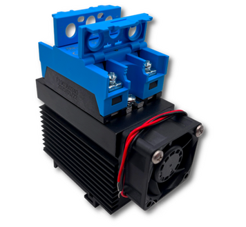
What is meant by “active” and “passive” cooling?“Passive” cooling refers to the normal convection process of a Power Controller, wherein the heat generated by the controller is transferred to the heat sink, which in turn is cooled by the surrounding ambient air. Since heat naturally rises, ambient air will flow upwards through the fins of the controller’s heat sink (when mounted properly) and gradually cool the power semiconductors. The cooler the ambient air, the more efficient the heat sink is at keeping the power components cool. Orientation of the heat sink to allow airflow is critical, as is the proper ventilation of the panel in which the controller is mounted. Without proper ventilation, the temperature of the heat sink can cause the ambient temperature to increase, which in turn causes the Power Controller to operate at higher temperatures and further increases the ambient. The temperature will eventually stabilize but the lack of adequate control over the amount of temperature rise can result in a thermal failure of the controller. “Active” cooling involves using fans or blowers to forcibly move air, measured in linear feet per minute (LFM), through the fins of the heat sink. This is the most effective form of cooling for a Power Controller as the air being ‘pushed’ through the fins significantly increases the efficiency of the controller’s heat sink. For example, if we switch 50 amps of load current through a Power Controller using a 90 amp solid state relay mounted to a 1.0°C/W heat sink in a 40°C ambient environment, then we can estimate that the base plate temperature of the SSR will settle at approximately 90°C; 50A = ~50W x 1.0°C/W heat sink = +50°C rise + 40°C ambient = ~90°C base plate temperature. Moving 500LFM of air through the fins of the same Power Controller’s heat sink improves its efficiency by roughly 65%. Given the same parameters as above, this would have an effect on the base plate temperature as follows; 50A = ~50W x 1.0°C/W heat sink x 0.35 adjustment factor = +17.5°C rise + 40°C ambient = ~57.5°C base plate temperature. In other words, the addition of a 120mm, 75CFM / 500LFM fan to the heat sink would reduce the base plate temperature by roughly 32.5°C (90.5°F). One note of importance is that the effect of forced air depends upon several different variables. This includes the amount of air that can flow into and out of the panel where the Power Controller is mounted, as well as how efficiently the air from the fan or blower is pushed through its heat sink (static back pressure). The most effective way to determine how much impact forced air has on a heat sink is to measure the actual base plate temperature during normal operation.
-
Does Thermal Fatigue Affect The Lifespan of HBControls Power Controllers?A common misconception with solid-state relays is that high operating temperatures negatively affect the lifespan of a Power Controller. This is partially true, primarily in cases where the operating temperature exceeds the maximum specifications of the solid-state relay. In fact, solid-state relays can operate safely and reliably for decades at high operating temperatures, as long as maximum ratings are not exceeded. Instead, the real concern revolves around thermal excursions - the rate and frequency at which the the temperature within the solid-state relay changes. Solid-state relays dissipate power in the form of heat during normal operation at a rate of approximately 1 Watt per ampere of load current. As a result, the internal temperature of the solid-state relay can increase rapidly if the heat sink to which it's mounted cannot adequately dissipate the heat. The subsequent expansion of internal components can eventually lead to thermal fatigue and the premature failure of the solid-state relay. This is our area of expertise. HBControls Power Controllers utilize highly efficient heat sinks to prevent the solid state relay from overheating during normal use. Datasheets for each controller provide maximum allowable current ratings in a given ambient temperature, eliminating the need for thermal calculations or heat sink selection. We also offer custom power controllers with active cooling solutions for high-current applications or situations where the SSR controllers are used in high-temperature environments.
-
What options are available for purchasing products from HBControls?We accept orders via phone, e-mail, fax or, for many products, directly from our website. Payment terms are also available for repetitive business needs, upon approval by our accounting team. You can contact us directly at 800.879.7918 / sales@hbcontrols.com. You can also contact one of our authorized distributors for competitive pricing; https://www.hbcontrols.com/distributors.
-
Is discounted pricing available for larger solid-state relay or power controller orders?Yes. The easiest way to obtain volume-based pricing is through one of our authorized distributors; https://www.hbcontrols.com/distributors. HBControls can also customize a quotation to fit your specific needs. Please contact us directly at 800.879.7918 / sales@hbcontrols.com if you’d like to discuss pricing options, or submit a quote request directly from our website - https://www.hbcontrols.com/quote
-
Does HBControls ship overseas?Yes. Our customer-base for solid-state relays and power controllers is global, so we can ship to any non-embargoed / non-sanctioned country. Please make sure you contact our agents if you are unsure whether we ship to your country or need additional information regarding overseas shipping. HBControls ships to over 100 international countries, including Canada, Denmark, Australia, Austria, Germany, Japan, The United Kingdom and others. Before ordering our products overseas, please make sure that you enquire about customs, duties and tax regulations with your country’s customs agency.
-
Will HBControls provide ongoing technical support after purchase?Yes. Working with our customers and potential customers is the part that we enjoy. One of the things that separates HBControls from our competition is the reliability and quality of our after-sale services. Our experienced staff will make sure you receive the best customer-service experience possible. Whether you need support for an existing project, a new project, or still trying to decide whether or not to use solid-state relays in your application, please contact us for support at any time; 800.879.7918 / sales@hbcontrols.com. Our ticket distribution system ensures all your calls and emails are quickly addressed by one of our customer support specialists.
-
Are there solid-state relays or power controllers available that are not published on the website?Yes. The products available on our website represent a small percentage of possible configurations. In many cases, these options/configurations are selectable within the online store page. However, if you can’t find the exact product to fit your needs, please contact us and let us help find the right product for your application; 800.879-7918 / sales@hbcontrols.com.
-
Can HBControls customize a product for a specific application?Yes. Our support team can work directly with you to design solid-state custom power controllers to fit your specific application needs. In most cases, customized products are developed for higher volume applications. However, depending upon the complexity of the design, we can also work with you to help with one-off/prototype projects. Please contact our support team if you would like a consultation on your specific requirements; 800.879.7918 / sales@hbcontrols.com.
-
Does HBControls warranty their work?Yes. Our solid-state relays and power controllers carry a standard one-year warranty. However, in case a manufacturing defect leads to product failure, it will be considered eligible for repair or replacement during its operational lifespan. If you have any questions regarding the quality of our products, want to voice your concerns or enquire about a return, please contact the HBControls Quality Control Department; Quality Control Manager: HBControls, Inc. 18 Rosary Lane Hyannis, MA 02601 Tel: (800) 879-7918 / Fax: (508) 676-7346, www.hbcontrols.com. HBControls will not be considered liable for any damage sustained apart from the repair or replacement of the equipment provided by the customer. HBControls takes no responsibility for additional parts, costs or labor incurred.